
The Nicolay Zaev Generator
Test report #3 from Sergey M. Godin
Created on 10-31-98 - JLN Labs - Last update 11-02-98
Hi guys!
Yesterday (10-30-98), I have conducted some experiments with the
new more high output voltages driver on a pair of darlington
transistors (U max=100V; Imax=20A; Ft=10MHz).

The main purpose of this experiment was to
increase a voltage on the variconds battery and to reduce working
frequency for increasing of the efficiency of the warm
conversion.
I want at once to say, that the chosen way of measurement of the
power of charge/discharge, offered by NIkolay Zaev, has appeared
is practically unsuitable for work with by an electronic switch.
In the initial moment the current of charge and discharge is
defined by internal resistance of the thermoconverter and
electronic switch. At enough abrupt fronts of a signal, the
internal resistance becomes undefined and introduces significant
errors in the current measurement.
It is very well visible at connection of the varicond to a + wire
or to a ground wire.Thus different transistors with by different
internal resistance under the charge/discharge mode work
unsimilar. Obviously, that at connection of the variconds to +
wire and under the work of a p-n-p transistor the current will be
max. The experimental data was presented for a meandr signal with
frequency 20Hz, at maximum voltage up to 87V.


For check of this assumption, consistently with the resistor of 3.9 Ohm included a resistor of 101 Ohm and 430 Ohm.

Voltage on the variconds battery under charging
via 100 Ohms,
T=50ms. Meander pulses

Voltage on the variconds battery under charging
via 0.5 Ohm
of inner thermoconverter resistence and pulses duration 300mks,
T=50ms .

Voltage on the variconds battery under charging
via 0.5 Ohm
of inner thermoconverter resistence and pulses duration 300mks,
T=50ms, a the resistor 3.9 ohms is added.
In the all tests a 90V power supply was used.

Further I has tried to evaluate influence of the signal fronts on the value of the discharge current. The load of a 36V and 0.12A lamp was used. The first case resistence was 3.9 + 0.5 ( internal resistanceof the thermoconverter). The second - only 0.5 Ohms, not including internalresistance of a transistor and connected wires.
![]()
As it is visible, the sharp increasing and amplification of the sound tracking, does not practically influence the value of the discharge current.
Below, visually, increasing of light bulb brightness nor has taken place.
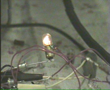
You may also hear
the sound of ferroelectric capacitors.
Conclusions: for more correct measurement
of CD energy it is necessary to use two sources of a CURRENT with
large internal resistance. Next week, I will try to give the
final answer Yes or Not, and if yes, then what the maximum power
can be received from 10mkF battery at room temperatures.
Sincerely yours,
Sergey Godin (10-31-98)
If you need more informations or if you have any suggestions send me your Feedback
![]() Email
: JNaudin509@aol.com
Email
: JNaudin509@aol.com
Return to the Zaev's Generator page or JLN Labs home page