A Negative Differential Resistance Oscillator with a Negistor
Created on 06-09-01 - JLN Labs
- Last update 06-16-01
All informations in this
page are published free and are intended for private/educational
purposes and not for commercial applications
You will find below a very simple experiment that anyone can perform with few and cheap electronic components. This experiment will demonstrate you how a very simple oscillator can be built with a component which shows a Negative Differential Resistance ( NDR ) effect when it is used properly.
There is no overunity effect here but this device is worth to be known because in this case the NDR component used does not seem to agree with the basic Ohm's Law : According to the Ohm's law an increase of the voltage produces an increase of the current, in this case, in the negative resistance region of the NDR characteristic curve, an increase of the voltage produces a decrease of the current. This NDR effect in semiconductors has been discovered by Leo Esaki, he has been awarded a Nobel Prize in 1973 for his discovery of the Tunnel Effect used in the Tunnel diode. A tunnel diode ( the Esaki diode ) is a special component which has been specially designed to operate in the negative resistance region. ( See "Field emission - Fowler-Nordheim tunneling" ). Some other components which produce the NDR effect are the Gunn diode and the Lambda diode.
The Tunnel diode has been patented by Leo Esaki : US4198644:Tunnel diode by Esaki; Leo 1980 ( see the full Esaki patent )
This NDR component is a common and cheap NPN transistor 2N2222A. ( see the 2N2222A datasheet )
Used in the reverse mode this transistor has been called "The Negistor" by Richard Phares ( see : http://www.keelynet.com/zpe/negistor.htm ).
You will see below the Voltage/Current curve characteristic of the Negistor in the NDR region :
So, it is very easy to build a NDR oscillator with a Negistor, see the diagram below :

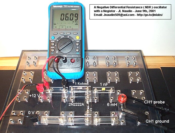
When the 12V DC power supply is switched on, the LCR circuit start to oscillate at about 60 KHz and remains stable
It is also possible to connect the Negistors in serie, this will allow to use more voltage/current at the DC input and thus this will give you more power at the output coil ( see below ). The coil can be also a primary coil of a transformer...
Above : With 3 Negistors connected in serie, you get about 97 Volts (pk-pk) across the coil L1 with 35V DC at the input...
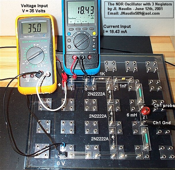
All the measurements (above) have been done with a DC power supply
See also : NDR Oscillator tests with Load
![]() NDR builders reports and tests feedback
:
NDR builders reports and tests feedback
:
Interesting documents to be read :
Theory of room temperature resonant tunneling devices ( RTD ) by Christian Strahberger - WSI
The Resonant Tunnelling Transistor ( RTT ) by Collin Moffat, Image Processing Group- Department of Physics and Astronomy Universty College London
For
more informations, please contact : ![]() JNaudin509@aol.com
JNaudin509@aol.com
Return to the CNR home page