The Glow Discharge Plasma Tests
Advanced Reduced Drag Aircraft project
By Jean-Louis Naudin
created on
February 15th, 2000 - JLN Labs
- Last update February 17th, 2000
New GDP tests - Feb 8th, 2000


Notes about the measurements (above) :
These tests has been conducted with the GDP only ( without the neon tubes ).
- The upper
left scope picture shows the Voltage and the
Current curves measured at the GDP output. The Voltage is set at
2kV/div, the current is set at 50mA/div ( the current has been
measured on the R1 non inductive 10 ohms
resistor, with
a x10 probe, the scope input channel ratio has been set to
1000mV/A ), the time base used is 50us/div. The right side of the
scope picture shows datas measured by the scope itself : on
Ch1(Voltage) : freq=6.024 kHz at 5kV and on Ch2(Current) : 154mA.
Notes : The setup of Ch1 and Ch2 channels used
for measuring the voltage and the current has been checked on an
external power supply ( see the Probes setup checking ), this avoid some eventual errors in
the channels calibration.
- The upper right scope picture, shows the third channel of the scope, this is the Math channel, ( Math=Ch1xCh2 ) this gives in real time the curve of the power flow. The "M" channel is set to 200W/div, the measured data on the right side "M RMS" is the Mean RMS ( Root Mean Square power ) =375.9 W
- The left
bottom scope picture, shows the same
channels ( Voltage/current in the XY Mode "Lissajous
method" ). This is better for measuring the Phase shifting
between voltage and current.
- The right bottom diagram,
shows the setup used during the measurement. ( The DC input power
is 39.47 Watts ( 30.6V DC @ 1.29A ). The voltage is measured with
a special x1000 High Voltage Probe
GE3830 ( max
working freq: 3MHz) (see the specs at the top of this page )
For the measurements, I have used a Tektronix oscilloscope THS720P, this is an independently floating and isolated channels scope and it has full floating measurement capability. The THS720P is used completly ungrounded and runs on its own internal batteries.
GDP tests - Feb 13th, 2000 ( Asymmetrical current )
To go further in the understanding of the current flow through the GDP Panel, I have built a current probe which uses a ferrite tore. The current probe is a 25uH toroidal coil with the main GDP wire through its main axis. The Textronix TX1-DMM is used for measuring the voltage induced when the current flows.
The "apparent" measured current is not equal in one branch of the GDP wire than in the other branch.
GDP tests - Feb 14th, 2000 ( Asymmetrical current with scope )
Notes about the measurements (02-14-00) (above) :
These tests has been conducted with the GDP only ( without the neon tubes ).
- The upper
left scope picture shows the Voltage and the
Current curves measured at the GDP output. The Voltage is set at
2kV/div, the current is set at 20mA/div ( the current has been
measured on the R1 non inductive 10 ohms
resistor, with
a x10 probe, the scope input channel ratio has been set to
1000mV/A ), the time base used is 50us/div. The right side of the
scope picture shows datas measured by the scope itself : on
Ch1(Voltage) : freq=6.981 kHz at 5.04kV and on Ch2(Current) :
28.4mA.
Notes : The setup of Ch1 and Ch2 channels used
for measuring the voltage and the current has been checked on an
external power supply ( see the Probes setup checking ), this avoid some eventual errors in
the channels calibration.
- The upper right scope picture, shows the third channel of the scope, this is the Math channel, ( Math=Ch1xCh2 ) this gives in real time the curve of the power flow. The "M" channel is set to 50W/div, the measured data on the right side "M RMS" is the Mean RMS ( Root Mean Square power ) =71.61 W
- The left
bottom scope picture, shows the same
channels ( Voltage/current in the XY Mode "Lissajous
method" ). This is better for measuring the Phase shifting
between voltage and current.
- The right bottom diagram,
shows the setup used during the measurement. ( The DC input power
is 56 Watts ( 31.5V DC @ 1.78A ). The voltage is measured with a
special x1000 High Voltage Probe
GE3830 ( max
working freq: 3MHz) (see the specs at the top of this page )
You may notice that the power gain seems lower than the previous measurements above, this seems due to the asymmetrical effect of current, a ground reference effect ( ? )... More tests need to be conducted with an ungrounded power supply, this will be done by powering all the GDP appartus with ungrounded batteries.
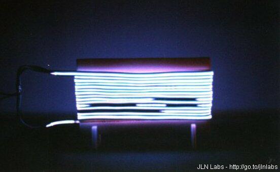
GDP tests - Feb 15th, 2000 ( ungrounded tests )
The purpose of this test is to use a GDP apparatus fully UNGROUNDED. I have placed all the testing setup on a thick polystyren plate ( 40mm) at 110mm above a wooden table. The GDP generator is powered by CdNi batteries cells ( 24 x 1.2V/1200mA). So, the GDP apparatus is able to run on its own ungrounded power source.


The current is measured with the Tektronix TX1-DMM used has a voltmeter and placed across a 10.6 ohms (non inductive) resistor in serie between the coil output and the GDP Panel. The DMM wires used have small length and are twisted (see the picture) to reduce significantly the parasitic RF inductions effects by the High Voltage.
The measurements with this fully ungrounded setup seem to confirm again the previous measured currents values, the voltmeter across the 10.6 ohms resistor ( at 6.55 kHz ) gives a current flow of about 95 mA at 5kV...
GDP tests - Feb 16th, 2000 ( ungrounded tests with EMI radiation influence tests )
A successfull
replication of the GDP device ( by Scott Little ) has recently shown that the
strong EMI generated by the GDP panel is able to generate real
problems about the measurements of the current flow.
So, I have conducted new tests to investigate this further. The
previous ungrounded setup ( powered by CdNi batteries ) has been
used here. The Tektronix
TX1-DMM
( accuracy +-0.002% between 20 Hz to 20 KHz in AC Voltage ) has
been placed on a plastic box and at 1 meter away from the GDP
Panel. The wires used with the DMM have been twisted so as to
reduce significantly the parasitic RF induction.
The Measured voltage accross a 10.6 ohms (non inductive) resistor is 0.929V AC ( at 5 KV AC @ 6.45kHz ) for an input of 49.4 Watts ( 29.4 V DC @ 1.68 A ).

The EM induction effects generated by the GDP panel in action has also been measured with a Tesla Monitor placed between a distance from 10 cm to 100 cm.

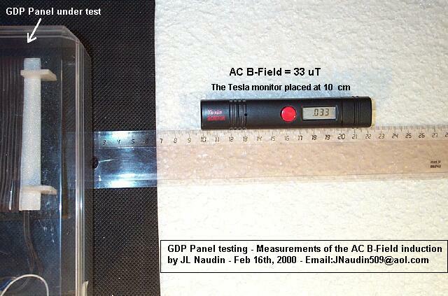
At 100 cm away from the GDP Panel the EM induction effects are significantly reduced.

The TX1-DMM has also been placed close to GDP panel in action and turned 90° right to check the EMI radiations influence. The wires used with the DMM have been twisted so as to reduce significantly the parasitic RF induction. You may notice that the position of the DMM has no major influence on the measurement.

The TX1-DMM has also been placed in an Electrostatic Shielded box. You may notice that the ES shield of the DMM has no major influence on the measurement.
GDP tests - Feb 17th, 2000 ( Heat Joule's effect )

A simple
100 ohms 1/4 Watt resistor has been placed in serie between the
coil output and the GDP Panel.
Only 2° C of differential temperature has been measured during a
2 minutes run.
So, today, the question is : If the current measured was really about 80 mA, why a 100 ohms (1/4 watt) doesn't heat ?
Some possible explanations can be found :
- 1) The current is a simple artifact : But, how we can explain that different measurement method and different instruments shows a similar values ?
- 2) The apparent power is not real : But, how we can explain that it is possible to light 6 LEDs ( 6x30 mA) in parallel or 2x30 Watts neon tubes in series with the GDP panel ?
- 3) This an EMI jamming effect : Does Electromagnetic Interferences can generates this can of artifact ?, This have been checked just above, and the digital innstruments doesn't seems influenced significantly by EMI.
- 4) This is an induction effect by ES longitudinal waves or Scalar type waves : Does a High Frequency ( 6 kHz ) Electrostatic Field ( at 5 kV ) is able to induce this kind of effect by longitudinal waves or scalar waves induction ?
This latest question is not yet solved, more ES shielding tests must be conducted by placing the entire GDP apparatus in a Faraday type cage.
The challenge is always open.... All constructive comments are welcome,
Stay Tuned....
Return to the previous GDP tests
Go to the Glow Discharge Panel construction
You may hear the Glow Discharge Panel sound
Analysis of the GDP sound wave
The Principle of the Active GDP Skin now explained...
Some interesting references, patents and links :
- The Industrial Plasma Engineering Group of the UTK Plasma Sciences Laboratory has been supported by NASA Grant NCC 1-223 since October 1, 1995 to develop the applications of a One Atmosphere Uniform Glow Discharge Plasma (OAUGDP) to aerodynamic boundary layer and flow control. These and related applications are described in U. S. Patent 5,669,583, "Method and Apparatus for Covering Bodies with a Uniform Glow Discharge Plasma and Applications Thereof". Wind tunnel measurements for this research were taken in the 7 X 11 inch Low Speed Wind Tunnel of the NASA Langley Research Center's Fluid Modeling and Control Branch, Hampton, VA.
- Boundary Layer Flow Control with a one Atmosphere Uniform Glow Discharge Surface Plasma. AIAA 98-0328, 36th Aerospace Sciences Meeting & Exhibit, Reno, Nevada, pp. 29.- Roth, J. Reece; Sherman, Daniel M.; Wilkinson, Stephen P. (1998)
-
"Steady-State, Glow Discharge Plasma". U.
S. Patent #5,387,842, Issued February 7,
1995.- Roth J. R., Tsai P. P. and Liu C.
- "One Atmosphere Uniform Glow Discharge Plasma". U.
S. Patent #5,414,324, Issued May 9,
1995. - Roth J. R., Tsai P. P., Liu C., Laroussi M. and Spence P.
D.
- "Method and Apparatus for Glow discharge Plasma Treatment
of Polymer Materials at Atmospheric Pressure". U.
S. Patent #5,456,972, Issued Oct 10,
1995. - Roth J. R., Tsai P. P., Liu C. and Wadsworth L. C.
- "Method and Apparatus for Covering Bodies with A Uniform
Glow discharge Plasma and Applications Thereof". U.
S. Patent #5,669,583, Issued Sept 23,
1997.- Roth J. R.
![]() Email : JNaudin509@aol.com
Email : JNaudin509@aol.com
Return to the Plasma Researches page


