IPS v1 :
Preliminary test results Tests by Jean-Louis
Naudin Created on
February 19, 2004 - JLN Labs -
Last updateFebruary 19, 2004 Toutes les informations et schémas sont publiés
gratuitement ( freeware ) et sont destinés à un usage personnel
et non commercial All informations and
diagrams are published freely (freeware) and are intended for a private use and a non commercial
use.
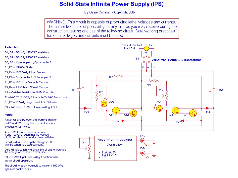
Below the basic diagram sent by the IPS'
inventor ( Ossie Callanan ). This diagram is published with
courtesy of Ossie Callanan.
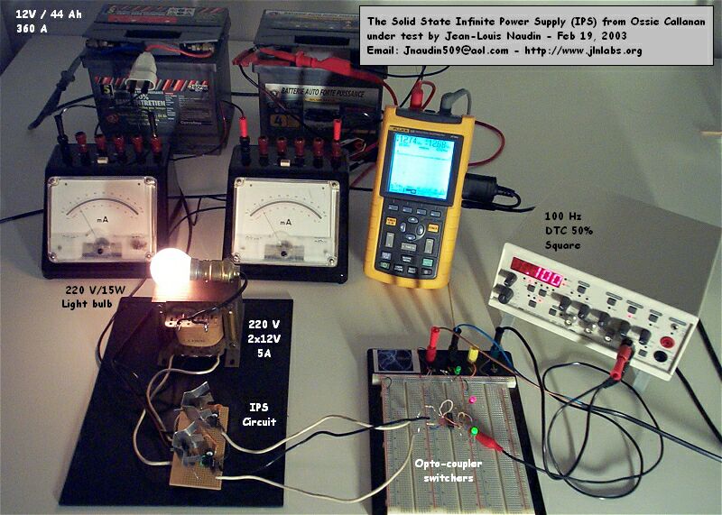
The
components used for the IPS v1.0 tests are :
Q1 : 2N6667, Q2: TIP 2955
Q3: 2N6387, Q4: TIP 3055
D1, D2: 1N4007
D3, D4: BY 228 ( 1500V/ 2.5A )
Q5, Q6 : 4N25
T1: 220V / 2x12V (5A)
B1, B2 : 12V/44Ah (360A) lead acid batteries
B3: 220V, 15Watts light bulb
Clock frequency : 100Hz square wave DTC 50%
Current flow from B1, B2 set to about 1A
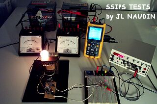
Above, the IPS-Switchers interface connected between the square
wave generator and the optocouplers (D5, D6).
The input of the IPS-Switchers interface is connected to a
function generator Centrad GF-763AF used as a square wave
generator.
Below the IPS circuit v1.0 during the test :
(
02-19-04 ) Tests results :
The Callanan's IPS circuit runs as described in his diagram. The
15 watts light bulb connected at the IPS's output works well, but
unfortunatelly, I have not yet been able to sustain the charge of
the two lead acid batteries used as the main power source.