Alternative
Fuels researches created on April 2,
2003 - JLN Labs - Last update
December 31, 2005 Toutes les
informations et schémas sont publiés gratuitement ( freeware )
et sont destinés à un usage personnel et non commercial All informations and
diagrams are published freely (freeware) and are intended for a private use and a non commercial
use.
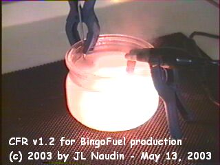
The bubbler is a tank containing a mixture
of water and hydrocabures (gasoline, diesel, kerosene,
crude oils and others derived from hydrocarbons...).
The hot gas flow coming from the exhaust
of the engine circulates by the outside part of the
reactor with a strong kinetic energy, that
contributes to bring up to very high temperature the
steel rod (being used as heat accumulator) contained
in the pyrolytic chamber. The gases cross the engine
and penetrate then in the bubbler containing the
water/hydrocarbures mixture. The vapor of the mixture
is strongly aspired by the vacuum created by the
engine intake and is pushed by the pressure coming
from the exhaust. The kinetic energy of the vapor is
increased considerably by the reduction of the
diameter in the pyrolytic chamber (by Venturi
effect). The combined effect of the high temperature
and the increase of the kinetic energy produces a
thermochemical decomposition ( molecular breakdown )
of the water/hydrocarbures mixture.
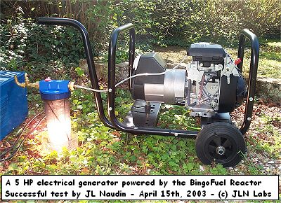
The endothermic reactor forms an
Electro-Plasma-Chemical unit (EPC) and it is now
possible to create a high-output fuel coming from the
decomposition of the water contained in the
water/hydrocarbures mixture. This fact is confirmed
by the presence of oxygen gaz (O2) in great amount
measured in the exhaust.
Le bulleur est un réservoir contenant un
mélange d'eau et d'hydrocarbures (essence, diesel, kérosène,
huiles usagées et autres dérivés d'hydrocarbures...
).
Le flux de gaz chauds provenant de
l'échappement du moteur circule par la partie
extérieur du réacteur avec une forte énergie
cinétique , cela contribue à porter à très haute
température la tige d'acier ( servant d'accumulateur
de chaleur ) contenue dans la chambre à pyrolyse.
Les gaz traversent le réacteur et pénètrent
ensuite dans le bulleur contenant le mélange
eau/carburant. Les vapeurs du mélange sont aspirées
fortement par le vide créé par l'admission et
poussées par la pression provenant de
l'échappement. L'énergie cinétique des vapeurs est
augmentée considérablement ( dans la partie bleu
clair ) par la réduction du diamètre dans la
chambre à pyrolyse ( effet de Venturi ). L'effet
combiné de la haute température et de cette
énergie cinétique accrue provoque la décomposition
thermochimique du mélange eau/carburant.
Le réacteur endothermique forme un
ensemble électro-plasma-chimique (EPC) permettant de
créer un carburant à haut rendement provenant de la
décomposition de l'eau contenue dans le mélange
eau/hydrocarbures est confirmée par la présence
importante d'oxygène O2 dans les gaz d'échappement.
At the Massachusetts Institute of
Technology (MIT), researchers are developing
a reformer, which, like the KCB&H one,
uses plasma for reforming hydrocarbons. The
advantage of a plasma reformer is that it can
use all forms of hydrocarbons, including
heavy oil fractions. In addition, the plasma
reforming can operate in pyrolytic mode
(thermal degrading of organic material
without air or oxygen) so that the carbon is
turned into soot. This eliminates the
formation of CO2. Plasma
technology allows for a more compact and
lighter design than traditional reformers
because the reaction occurs much faster.
MIT is studying use of the plasma reformer
in the pyrolytic, partial oxidation and steam
reforming methods mode. MIT's
"Plasmatron" operates at
temperatures of over 2,000 oC, and
the amount of hydrogen produced is around
80-90%. The main disadvantage with plasma
reforming is its dependency on electrical
power. MIT hopes to lower the need for
electricity to 5% of the fuel's
combustibility caloric value through heat
recycling and a better reactor design; today
it is 20%.
[L. Bromberg et al 1997/1998]
"Avant son installation, le
tracteur consommait 12-15 L/h.
Lors du dernier essai contrôlé avec un broyeur de 3
mètres pendant 8 heures d'affilée, la consommation
de gazole s'est stabilisée à 7.5 L/h pour une
consommation d'eau de 1.7 L/h."
SPAD
Le SPAD(c) est un
optimiseur compact de performances pour les moteurs
diesel et essence, dérivé du PMC Pantone, proposé
par APTE. La consommation de carburant et la
pollution sont fortement réduites...
<< This report is one in a series of
emergency technology assessments sponsored by the
Federal Emergency Management Agency (FEMA). The
purpose of this report is to develeop detailed,
illustrated instrucions for the fabrication,
installation, and operation of a biomass gasifier
unit (i.e. a "producer gas" generator, also
called a "wood gas" generator) which is
capable of providing emergency fuel for vehicles,
such as tractors and trucks, should normal petroleum
sources be severely disrupted for an extended period
of time. These instructions have been prepared as a
manual for use by any mechanic who is reasonably
proficient in metal fabrication or engine repair.
Fuel gas, produced by the reduction of coal
and peat, was used for heating as early as 1840 in
Europe and by 1884 had been adapted to fuel engines
in England. Prior to 1940, gas generator units were a
familiar, but not extensively utilized, technology.
However, petroleum shortages during World War II led
to widespread gas generator applications in the
transportation industries of Western Europe.
(Charcoal burning taxis, a related application, were
still common in Korea as late as 1970.) The United
States, never faced with such prolonged or severe oil
shortages, has lagged far behind Europe and the
Orient in familiarity with and application of this
technology. However, a catastrophic event could
disrupt the supply of petroleum in this country so
severely that this technology might be critical in
meeting the energy needs of some essential economic
activities, such as the production and distribution
of food. >>