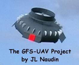
The GFS-UAV project
A Coanda effect flying saucer
created on March 10, 2006 - JLN
Labs - February 25, 2007
Toutes les
informations et schémas sont publiés gratuitement ( opensource
) et sont destinés à un usage personnel et non commercial
All informations and
diagrams are published freely (opensource) and are
intended for a private use
and a non commercial use.
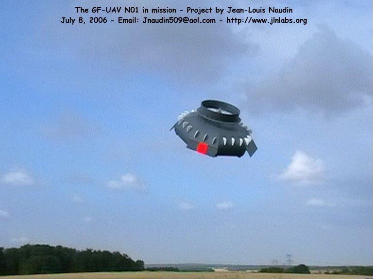
The GFS-UAV, propelled by an
electric engine, uses the Coanda effect to take off vertically,
fly, hover and land vertically ( VTOL ). There is no big rotor
like on an helicopter and the flight is very stable and safe for
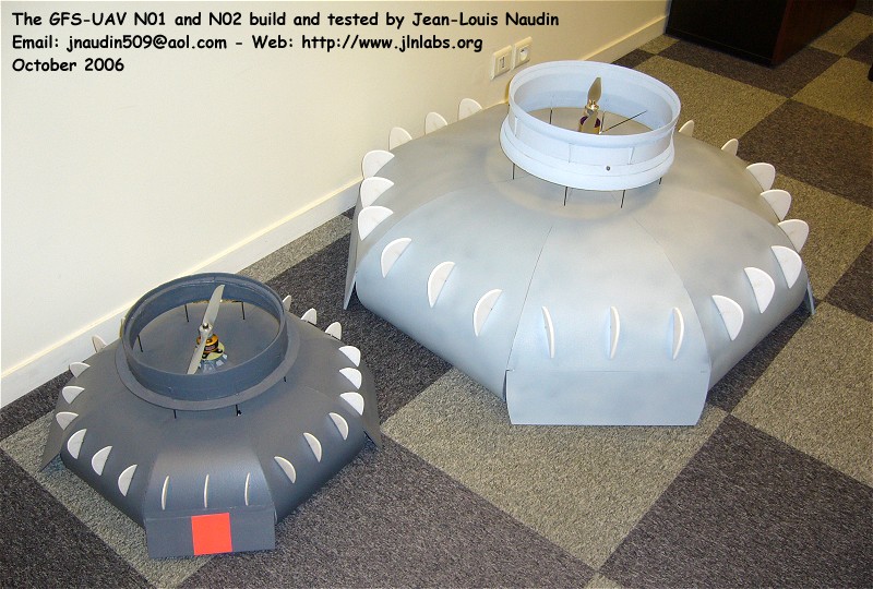
the surrounding. The design of the GFS-UAV N-01A is based on the
Geoff Hatton' flying saucer from GFS Project limited.
Le GFS-UAV,
propulsé par un moteur électrique, utilise l'effet Coanda pour
décoller verticalement, voler, faire du stationnaire et atterrir
verticalement ( VTOL ). Il n'y a pas un grand rotor comme sur un
hélicoptère et le vol est très stable et sûr pour
l'environnement. Le model du GFS-UAV N-01A est basé sur la
soucoupe volante de Geoff Hatton de GFS Project limited.
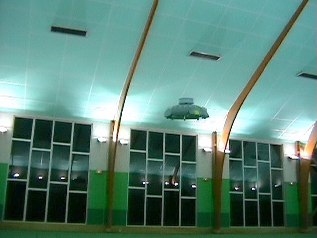
Dec
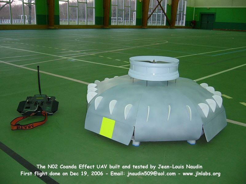
19, 2006 :
The BIG Coanda Saucer N02 has done successfuly its 1st
flight
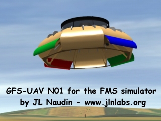
 BONUS
: The
GFS-UAV N01 for the FMS flight simulator
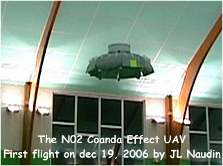
Dec 19, 2006 : FIRST FLIGHT of the BIG Coanda
Saucer N02
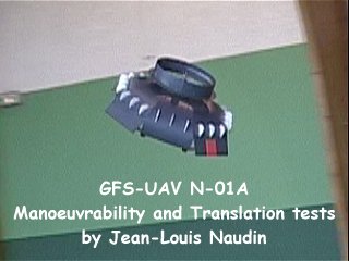
Manoeuvrability and translation test flights
at HIGH
SPEED
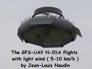
Outdoor test flights with a wind speed up to
10 km/h
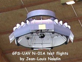
New improvements of the model N-01A
(Woow...)
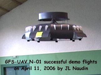
Successful hovering at 3 meters above the
ground
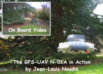
The GFS-UAV in action with a video-camera
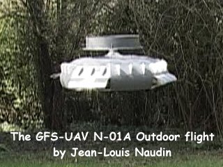
Photos and a video of the outdoor test
flights
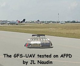
Tests
flights videos on AFPD and genesis of the project
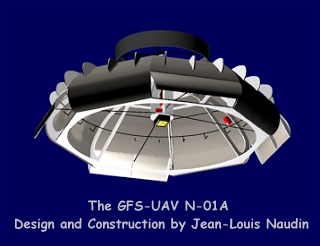
The GFS-UAV N-01A : Full plan and
construction details
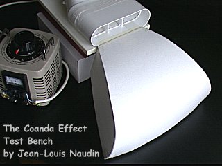
The Coanda Effect Test Bench ( CETB )
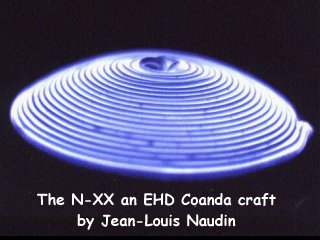
The N-XX an EHD Coanda Effect craft
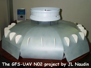
The big UAV N-02 construction details
GFS-UAV Project LOGBOOK
March 10, 2006 : Begining
of the project - First test flights on AFPD
simulator
March 17, 2006 : Computer
design of the true UAV model N-01A
March 19, 2006 : Full
plan and construction details about the UAV N-01A
released on the web
March 30, 2006 : 1st preliminary tests of the
GFS-UAV N-01A in laboratory.
March 31, 2006 : Several lift-off and
hovering have been done successfully in the lab.
April 2, 2006 : The Coanda Effect Test Bench
(CETB), a very useful engineering tool
April 5, 2006 : Improved trust and better
stablity with the streamlined body around the
propeller
April 7, 2006 : Successful
OUTDOOR tests flights
April 9, 2006 : On Board Video-transmission
with the N-01A
April 11, 2006 : Successful demo and test
flights in a wide open space
April 12, 2006 : Some impellers tested in the
lab
April 16, 2006 : The N-XX project,
an EHD Coanda effect craft
April 18, 2006 : New improvements of the
model N-01A (Woow...)
April 23, 2006 : Outdoor test flights with a
wind speed up to 10 km/h
April 25, 2006 : Manoeuvrability and
translation test flights at HIGH
SPEED
May 17, 2006 : The construction of
the UAV model N02 is now started (updated
on July 5, 2006)
October 17, 2006 : UAV N01 flight test/demo at
the ENSMP
December 12, 2006 : Training flights with the
UAV N01
December 19, 2006 : FIRST FLIGHT of the BIG
model N02
Documents, links and references :
PATENTS from GFS
Projects Ltd :
Inventor
:HATTON GEOFFREY (GB)
Applicant: GFS PROJECTS LTD (GB)
| Abstract of GB2424400 |
| To prevent the
spin of a craft designed to move though, or
on a surface of a fluid, means are provided
to vary the effective surface area of an
aerofoil 6. The craft may be of the type in
which a fan 2 directs fluid over a
dome-shaped canopy 1 utilising the Coanda
effect to generate lift, a plurality of
aerofoils 6 being used to counter unwanted
rotation of the canopy caused by a reaction
to the rotation of the fan. Each aerofoil 6
may be driven into or out of a respective
slot by means of an actuator controlled by a
signal generated in response to comparison of
an output signal, produced by an optical or
piezoelectric gyroscope, with a desired
attitude set by a steering mechanism. The
aerofoils 6 may be located where the angle of
attack in relation to the airfiows 7, 14
produced by the fan 2 is significantly
dependent upon fan speed. |
| Abstract of GB2424405 |
| In a craft
having a rotor 9A, 9B, 9C producing a flow
over an aerodynamic (eg. domed) surface 1, to
create lift or thrust, the gyroscopic effect
of the rotor, when driven at full power, is
such as to give the craft positive stability.
The rotor may comprise part of a radial flow
fan 2, having blades 9C, and a heavy annular
magnet 9B cooperating with fixed coils 7A for
effecting drive of the rotor. The resulting
angular momentum of the rotor may afford
gyroscopic stability enabling the craft to
hover close to the ground or a vertical
surface. Pitch and roll control may be
achieved by vanes PV1, PV2, RV1, RV2
controlled electronically in response to
rotation sensed by optical gyroscopes S1, S2
and taking gyroscopic precession into
account. |
| Abstract of GB2424406 |
| A thrust
generation arrangement comprises means 3 to
causes fluid to flow over a surface 1 of
double convex curvature, the surface 1
causing the fluid to divert from a radial
flow towards an axial direction by the Coanda
effect. The radius of curvature of the
surface 1 decreases progressively less
rapidly in a downstream direction. The
arrangement may be used to propel a vertical
take-off aircraft, the fluid may be caused to
flow by a radial fan 3, and the surface 1 may
be dome shaped. |
| Abstract of GB2424463 |
| A vehicle,
preferably an aircraft, comprises an impeller
(3, fig 2) which in use causes fluid to flow
over a surface 1 of the vehicle and produce
lift or thrust via the Coanda effect. An
intervention mechanism 7 is used to energise
a boundary layer 10 of the fluid on the
vehicle surface 1 so as to control the point
at which separation of the boundary layer 10
from the vehicle surface 1 occurs. The
intervention mechanism 7 can thereby operate
to control the steering of the vehicle. The
intervention mechanism may comprise a
vibrating diaphragm 8 and/or a flow of fluid
though an opening 6 on the vehicle surface,
or a vortex generator. |
|
For more
informations, please contact Jean-Louis Naudin : JNaudin509@aol.com
return to
the UAV home page

visitors since March 10, 2006


